Einzugsgebietsfenster/en: Unterschied zwischen den Versionen
Keine Bearbeitungszusammenfassung |
(Übernehme Bearbeitung einer neuen Version der Quellseite) |
||
| (13 dazwischenliegende Versionen von 3 Benutzern werden nicht angezeigt) | |||
| Zeile 97: | Zeile 97: | ||
===Temperature=== | ===Temperature=== | ||
The temperature can be entered either as a time series or as an average temperature and if necessary scaled with an annual and/or daily | The temperature can be entered either as a time series or as an average temperature and if necessary scaled with an annual and/or daily pattern. | ||
===Evaporation=== | ===Evaporation=== | ||
For the [[Special:MyLanguage/Catchment Area#Evaporation VP(t)|evaporation]] there is the possibility to connect a time series, to define | For the [[Special:MyLanguage/Catchment Area#Evaporation VP(t)|evaporation]] there is the possibility to connect a time series, to define an annual evaporation or to use the values from a previously created [[Special:MyLanguage/Evaporation Window|evaporation calculation]]. | ||
===Base | ===Base Flow: Mean Value=== | ||
The base flow start value can be specified as a mean run-off rate. | |||
For soil moisture calculation, this value determines the start content (recalculated) for the basic runoff storage tank. From the l/s km² given here a volume is recalculated, which together with the retention constant of the base runoff gives this value for the base | For the soil moisture calculation, this value determines the start content (recalculated) for the basic runoff storage tank. From the l/s km² given here a volume is recalculated, which together with the retention constant of the base runoff gives this value for the base flow at the beginning of the simulation. | ||
<div class="mw-translate-fuzzy"> | |||
===Snow=== | ===Snow=== | ||
{{TODO}} | |||
</div> | |||
== Sequence assignment== | == Sequence assignment== | ||
[[Datei:Einzugsgebietsfenster_Abflaufzuordnung_EN.PNG|right]]If the catchment element has more than one runoff element, the different runoff components can be sent to different runoff elements in the | [[Datei:Einzugsgebietsfenster_Abflaufzuordnung_EN.PNG|right]]If the catchment element has more than one runoff element, the different runoff components can be sent to different runoff elements in the runoff assignment tab. By default, the entire drain goes to the first drain. Using drag&drop, the drain components shown on the left can be dragged to the drains on the right of the screen to make or break the connection. By clicking on the drain components, the respective connection to the drain is marked red. Clicking on the drains will mark the connections of all inflowing drain components. | ||
Aktuelle Version vom 15. Februar 2021, 14:10 Uhr
The properties window of the sub-basin can be opened by double-clicking on the element symbol in the flow network map ![]() or by right-clicking → Properties.
or by right-clicking → Properties.
It has the three tabs Properties, Simulation and Outflow network. In the upper part of the window there are also three buttons - one for saving , one for applying values, as well as settings from other sub-basin elements in the same database (i.e. also from other variants and projects)
, and one for closing the window. It is important to know that the sub-basin window also saves data automatically when closing.
Properties
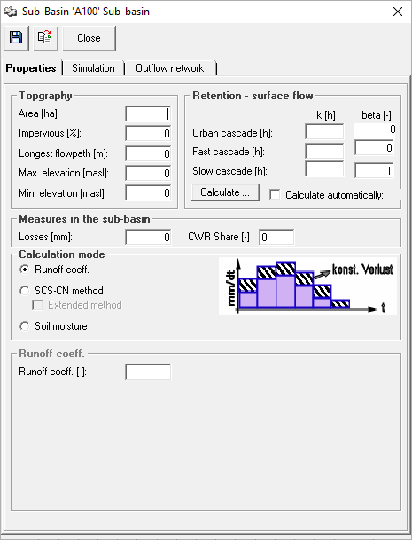
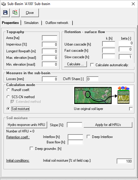
In the properties tab, general sub-basin characterstics and parameters such as topography, surface runoff retention and measures are entered. Furthermore, the calculation mode for determining the fraction of precipitation which contributes to the runoff is selected and the required parameters are entered.
Topography
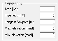
The data to be entered in the topography section is typically determined in a GIS. The area of the sub-basin is crucial for the amount of generated runoff, since the precipitation is processed into the precipitation-runoff-model as precipitation height [mm] and, therefore, has to be scaled with the area.
The degree of imperviousness dictates the percentage of impervious area in the sub-basin and describes the proportion that runs off as urban surface runoff. The urban surface runoff is calculated separately from the remaining natural surface runoff and retained in a separate storage cascade. The discharge sequence assignment can also be used to assign this runoff to a different outflow element. The values for longest flowpath and maximum and minimum elevation are used to automatically calculate the surface runoff retention constants.
Retention - Surface Flow
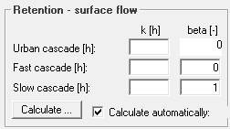
The discharge concentration parameters of the surface flow are entered in the Retention - surface flow section. Using the Calculate button, they can be automatically calculated from the input values in the topography section. Attention: If the box calculate automatically is checked, the parameters, that are calculated automatically, based on the current input in the topography section, are used for the simulation. If the retention constants of the surface runoff shall be changed and calibrated, the check mark must be removed first.
Measures in the Sub-Catchment
In the Measures in the sub-catchment section, the user can enter depression losses. Using the Irrigation button an irrigation scheme can be defined and connected.
Calculation Mode
For the calculation of the infiltration and runoff-effective precipitation, Talsim-NG offers the following three calculation options. You can choose among them in the Calculation mode section.
1. Runoff Coefficient
If the runoff coefficient method is selected, a constant runoff coefficient between 0 and 1 can be entered. This determines the amount of precipitation that flows as runoff after deducting losses.
SCS-CN Method
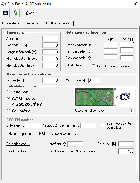
If the SCS-CN method has been selected as the calculation method, the CN-value and the 21-day rainfall index can be entered below the calculation mode section. In addition, the check box can be used to indicate whether a constant loss should be considered in the calculation.
Extended Method
In the extended method, not only the direct surface runoff is determined, but also a soil moisture simulation is carried out for the infiltrated amount, and the component's interflow and base flow are determined. For this purpose, the hydrological response units must be created using the corresponding button. The retention coefficients for interflow and base flow, which are used for the calculation of the discharge concentration, are also defined. Moreover, the initial soil moisture can be set (default setting: 100%). If the checkbox Use original soil layer is activated, the soil layers are used as provided by the user. By default, the soil layers are grouped into three internal calculation layers (infiltration layer, root layer and transport layer).
Soil Moisture
The soil moisture calculation option is the calculation option that requires the most parameters. The catchment is divided into individual hydrologic response units (HRUs) using the hydrologic response units button. The sub-basin window provides the option to assign a uniform slope to all HRUs.
The retention coefficients for interflow and base flow, which are used for the calculation of the discharge concentration, are defined.
If the calculation of the deep interflow and/or the deep base discharge is also activated via checkboxes, the retention constants must also be entered for these two discharge components, as well as the desired division ratio for the base discharge into base discharge and deep base discharge. The initial soil moisture can also be entered (default setting: 100%).
If the checkbox Use original soil layer is activated, the soil layers are used as provided by the user. By default, the soil layers are grouped into three internal calculation layers (infiltration layer, root layer and transport layer).
Simulation Settings
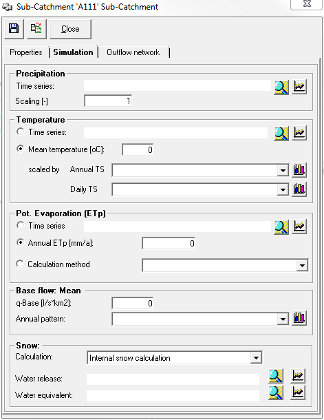
The simulation settings tab is used to define the loads effecting the catchment area and to select the calculation type for the snow calculation.
The selection of the time series is done with the button Selection ![]() . The button Display
. The button Display ![]() opens a window with the time series graphics.
opens a window with the time series graphics.
Constant hydrographs can be connected via their respective selection menus and can be deleted with the DELETE key. By clicking the button Show chart ![]() , the hydrograph window opens, where the chart can be edited directly. It is important to note that the hydrograph can also be connected to other places in the model and that the changes are valid everywhere. If you want to modify a chart only for the current catchment area, a copy has to be created and connected before.
, the hydrograph window opens, where the chart can be edited directly. It is important to note that the hydrograph can also be connected to other places in the model and that the changes are valid everywhere. If you want to modify a chart only for the current catchment area, a copy has to be created and connected before.
Precipitation
Precipitation can be directly connected as a time series and can be scaled by a factor if necessary. If no long-term simulation but a short-term forecast with model rain is to be calculated, the settings are controlled directly via the short-term forecast.
Temperature
The temperature can be entered either as a time series or as an average temperature and if necessary scaled with an annual and/or daily pattern.
Evaporation
For the evaporation there is the possibility to connect a time series, to define an annual evaporation or to use the values from a previously created evaporation calculation.
Base Flow: Mean Value
The base flow start value can be specified as a mean run-off rate.
For the soil moisture calculation, this value determines the start content (recalculated) for the basic runoff storage tank. From the l/s km² given here a volume is recalculated, which together with the retention constant of the base runoff gives this value for the base flow at the beginning of the simulation.
Snow
Sequence assignment
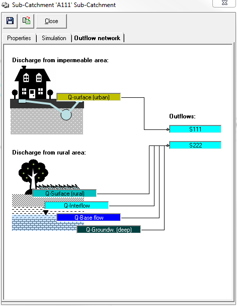
If the catchment element has more than one runoff element, the different runoff components can be sent to different runoff elements in the runoff assignment tab. By default, the entire drain goes to the first drain. Using drag&drop, the drain components shown on the left can be dragged to the drains on the right of the screen to make or break the connection. By clicking on the drain components, the respective connection to the drain is marked red. Clicking on the drains will mark the connections of all inflowing drain components.
