Unterteilung in Systemelemente/en: Unterschied zwischen den Versionen
Ferrao (Diskussion | Beiträge) (Die Seite wurde neu angelegt: „== Grid-based subdivision==“) |
Keine Bearbeitungszusammenfassung |
||
| (49 dazwischenliegende Versionen von 4 Benutzern werden nicht angezeigt) | |||
| Zeile 1: | Zeile 1: | ||
<languages/> | <languages/> | ||
{{Navigation|vorher= | {{Navigation|vorher=Systemabgrenzung|hoch=Arbeitsschritte zur Modellerstellung|nachher=Systemlogik}} | ||
In order to divide a water resources system into individual [[Special:MyLanguage/Beschreibung der Systemelemente|system elements]] it is vital to consider the problem which the model is used for and the existing data basis. | |||
Basically there are two | Basically there are two possible ways for the division of the system. It can be divided either catchment-based or grid-based. In addition, all hydrological structures relevant to the problem must be identified and represented by a suitable [[Special:MyLanguage/Beschreibung der Systemelemente|system element]], e.g. dams by [[Special:MyLanguage/Speicher|storage]], extractions by [[Special:MyLanguage/Verbraucher|consumer]], etc. Often there are several feasible solutions. | ||
The | The preliminary work for dividing a river basin is usually done with a GIS. | ||
==Catchment | ==Catchment-based Division== | ||
Criteria for the | Criteria for the division can be: | ||
* | *Catchment properties (topography) | ||
* Punctual changes of the outflow by | * Punctual changes of the outflow by | ||
** Inflows | ** Inflows | ||
** Point sources | ** Point sources | ||
** | ** Extractions | ||
* Location of hydrological structures | * Location of hydrological structures | ||
* | * Location of gauging stations | ||
* | * Flow type and geometry | ||
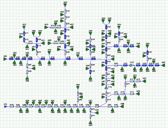
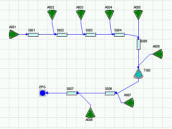
The | The results of this division are digital catchment boundaries and river sections. If the available data initially results in a rough division, it can be subdivided even further, especially if, due to the problem at hand, certain processes in the waterbody can no longer be represented with the intitial division. In the following, a high resolution water resources system is compared to a low resolution water resources system: | ||
{| class="wikitable | {| class="wikitable" | ||
|- | |- | ||
| [[ | | [[Datei:System_räumlich_hochaufgelöst.png|400px]] || [[Datei:System_räumlich_geringaufgelöst.png|400px]] | ||
|- | |- | ||
| | | | ||
*As the accuracy of system mapping increases, the importance of hydraulics in waterbodies increases. | *As the accuracy of system mapping increases, the importance of hydraulics in the waterbodies increases. | ||
*The parameters of the | *The parameters of the runoff concentration only refer to the surface runoff in the corresponding sub-catchments, resp. interflow and base flow. | ||
*The illustration of the | *The illustration of flood-routing within the waterbodies is possible. | ||
|| | || | ||
*Simple approaches to the calculation of | *Simple approaches to the calculation of runoff generation usually manage better with a rough system illustration. | ||
*Both the surface runoff in the | *Both, the surface runoff in the sub-catchments and the flood-routing that occur in the waterbodies are included in the parameters of the runoff concentration. | ||
*The illustration of the | *The illustration of flood-routing within the waterbodies is hardly possible. | ||
|- | |- | ||
|} | |} | ||
[[ | [[Datei:Teilgebiet_Auswahl_Systemelemente.png|thumb| Sub-catchments can be defined via a [[Einzugsgebiet|Rainfall-Runoff Model]][[Datei:Systemelement001.png|20px]] or can be visualised through a [[Special:MyLanguage/Einleitung|hydrograph]][[Datei:Systemelement002.png|20px]] at the output]] | ||
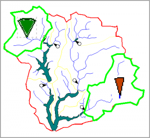
The next step is to decide which system elements are to be used to map the | The next step is to decide which system elements are to be used to map the sub-catchments, depending on the problem and the data basis. Alongside the system element [[Special:MyLanguage/Einzugsgebiet|sub-basin]], which brings the load into the system via a precipitation-runoff simulation, the system element [[Special:MyLanguage/Einleitung|point source]] can feed the outflow from the sub-catchment directly into the system via a hydrograph. The latter is of course only possible if a hydrograph is available. Then it is the solution using the fewest computational resources, which in addition (with good quality of the input data) also illustrates the actual outflow behavior in a realistic manner. If, however, for example, a forecast is to be calculated with changed land use conditions or if the hydrograph is not long enough, it is advisable to use the system element [[Special:MyLanguage/Einzugsgebiet|sub-basin]]. In Talsim-NG the selection of the system element for sub-catchments can also vary from sub-catchment to sub-catchment. | ||
Once the system elements are defined, the [[Special:MyLanguage/Systemlogik|flow network]] is created, i.e. the flow relationships between the elements are defined. | Once the system elements are defined, the [[Special:MyLanguage/Systemlogik|flow network]] is created, i.e. the flow relationships between the elements are defined. | ||
== Grid-based | == Grid-based Division== | ||
In grid-based division, water is generally passed from one cell to the next according to its flow direction. | |||
The transfer from one cell to the next varies depending on the flow component: | |||
* | * Surface runoff is incorporated into the runoff generation process of the next cell, i.e. it is treated like additional precipitation. | ||
* Interflow | * Interflow is fed into the cascade of storages of the next cell's interflow. | ||
* | * Base flow is fed into the cascade of storages of the next cell's base flow. | ||
Aktuelle Version vom 30. August 2021, 11:49 Uhr
In order to divide a water resources system into individual system elements it is vital to consider the problem which the model is used for and the existing data basis.
Basically there are two possible ways for the division of the system. It can be divided either catchment-based or grid-based. In addition, all hydrological structures relevant to the problem must be identified and represented by a suitable system element, e.g. dams by storage, extractions by consumer, etc. Often there are several feasible solutions.
The preliminary work for dividing a river basin is usually done with a GIS.
Catchment-based Division
Criteria for the division can be:
- Catchment properties (topography)
- Punctual changes of the outflow by
- Inflows
- Point sources
- Extractions
- Location of hydrological structures
- Location of gauging stations
- Flow type and geometry
The results of this division are digital catchment boundaries and river sections. If the available data initially results in a rough division, it can be subdivided even further, especially if, due to the problem at hand, certain processes in the waterbody can no longer be represented with the intitial division. In the following, a high resolution water resources system is compared to a low resolution water resources system:

The next step is to decide which system elements are to be used to map the sub-catchments, depending on the problem and the data basis. Alongside the system element sub-basin, which brings the load into the system via a precipitation-runoff simulation, the system element point source can feed the outflow from the sub-catchment directly into the system via a hydrograph. The latter is of course only possible if a hydrograph is available. Then it is the solution using the fewest computational resources, which in addition (with good quality of the input data) also illustrates the actual outflow behavior in a realistic manner. If, however, for example, a forecast is to be calculated with changed land use conditions or if the hydrograph is not long enough, it is advisable to use the system element sub-basin. In Talsim-NG the selection of the system element for sub-catchments can also vary from sub-catchment to sub-catchment.
Once the system elements are defined, the flow network is created, i.e. the flow relationships between the elements are defined.
Grid-based Division
In grid-based division, water is generally passed from one cell to the next according to its flow direction.
The transfer from one cell to the next varies depending on the flow component:
- Surface runoff is incorporated into the runoff generation process of the next cell, i.e. it is treated like additional precipitation.
- Interflow is fed into the cascade of storages of the next cell's interflow.
- Base flow is fed into the cascade of storages of the next cell's base flow.

